Window Relay Conversion Kit for the Jaguar XJS

| Last modified 2005 APR 07 04:37:57 GMT |
There are no wires to cut, and the modification is completely removeable should you have some reason to want to do so (though I can't rightly imagine WHY one would want to remove it). This was an important consideration when I went about designing this modification - I'm reluctant to cut my Cat.
Another benefit to this mod, versus doing it via other suggested methods, is that the modification is central - there is only one place you have to open in order to perform the modification (and you should open the console to remove the original switches just to clean them ANYWAY) -- unlike opening up both of the door panels and installing relays in there (and that plan necessitates running an additional power lead to each door to power the windows since the power leading to them currently would be low current switching through the switches).
I should be forthright in stating that I'm not in the business of producing kits or performing service on other people's automobiles -- these kits are the result of having to design and assemble one for my own needs, and it seemed such a waste to not share the solution. If this disturbs you, well, at least I've told you, right?
Although I had originally constructed a quantity of these kits (as a function of ordering enough relays and wire so as to not waste money on shipping), I no longer have any kits, assembled or otherwise. When I get some time, I'll see to posting some manufacturer part numbers and the wiring diagram (which isn't at all complicated, but there are a number of wires in the harness). This document continues to be published because I provide some technical data about the window switches herein. please disregard comments referring to kits and sales of same.
A side note - the bezel for the factory convertible models appears like it is a drop-in replacement for the coupes (or late-model cabrios), offering THREE window-switch sized sockets - meaning that those looking for a place to mount an extra switch (say for the Garner or Napoli environmental mods) might be interested in checking this out.
The cost largely is a function of my investment in time (when you get the kit, you'll note that it is fully assembled, rather than the collection of parts I originally set out to provide). After setting forth to produce a concise document describing the assembly process and the tools necessary to perform it properly, I realized that a vast majority of individuals would be missing one or more tools, and/or would be unsure of their skills in performing specific assembly tasks. By providing it as a complete kit, I can be sure that what I send to you is operational and will require a minimal amount of work on your part to install. Unfortunatley, the detail work in producing the wiring harness and assembling the relays doesn't benefit appreciably from economies of scale (it takes over two hours to cut, strip, solder, crimp and assemble) -- but at least having assembled several already, when I'm doing it, I already have an idea of what goes where, which reduces the goof factor.
I physically check the operation of the relay harnesses on an actual 12V power source with a switch to ensure that the wiring and polarity is correct and that the relays are operational when delivered.
The installation process is quite simple: open your console ("ski slope"). This varies between model years -- earlier models have a flat black console, with (I believe) three screws, which you remove, and then carefully lift the console up (may require unscrewing the gearshift knob). Later HE models (1988 and onwards) have a wood veneer console, which is a bit more work to remove - you've got to open the console storage compartment, and remove the two screws holding the snap retainer down, then remove the screw underneath that. You MIGHT possibly be able to lift up the console, but chances are that you'll need to remove the cigarette lighter and speed control switches on either side of the console (which may require removal of the ashtrays on either side) to access the nuts underneath them which retain the console at midpoint. Goofy way of doing it all.
Once the console is lifted upwards (barring really unusual complications, this is a 5-10 minute task, with the newer consoles, and less with the old ones), you have access to the bottom of the switches. Note which harness belongs to which switch (a piece of tape to mark driver side may be useful here), then disconnect the harness and confirm which sort of switch you have.
I'm aware of three types of switches (and unless you have a late-late XJS model, this is all there is). All switches have the contacts numbered on the bottom of the switch. Note that my convention is to use the same contact numbers for the MATED contacts on the socket, which is a MIRROR of the switch (side-to-side), just as if you flipped it over and are looking at the bottom.
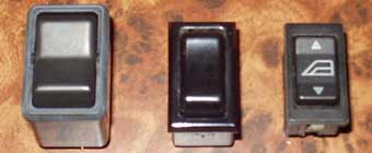
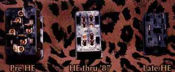
Pre-HE (1975-1981). 1/4" spade contacts, arranged in a skewed fashion. This switch is the largest, at 1 3/16" wide by 1 3/4" high, with a matte (non-gloss) finish.
	   |	(1)

	 -- --	(2 4)

	-- --	(3 5)

	 |	(6)
1 and 6 are outputs to the motor - +1/-6 = DOWN, -1/+6 = UP. 5 is +V supply, 2 is ground. 4 from master runs to 5 on slave, 3 on master runs to 2 on slave. 4 and 3 are N/C on slave. For my kit, the standard relay assemblies are provided (as for the late HE model), an additional couple of splitters, and a jumper so that the second harness is wired appropriatley. In the neutral state, there is continuity across 2+3 and 4+5 (which is how a slave switch is driven).
Early HE (1981-1987). Bullet connectors - six round posts on bottom of switch. Face of switch is devoid of markings and is a high gloss. 1" wide by 1 11/16" high at the bevel. There are two poles (two columns), of three posts each - two are situated near each other, and one a bit further away, something like this:
	O  O	(1 2)
	O	(3 4)
	   O	(5 6)
	O  O	(7 8)
In the neutral state, there is continuity across 2+6 and 3+7. The relay kit for these switches differs from the others, since the bullet connectors have to be HANDMADE. This is an annoying process, cutting the individual bits and deburring them. Additionally, because of the way that the switch is wired, both poles of the switch need to be employed, which requires a split in the +V lead (this is all handled in the kit, so don't fret).
Late HE (1988 and onward). 1/4" spade connectors. Switch is 7/8" wide by 1 1/2" high at the bevel. Face of switch is matte (flat non-shiny), has a pictogram of a window, with up and down arrows. These also have two columns of contacts, although they're skewed, but they're equally spaced, and are spade ("blade") contacts. One (labelled 6) is missing the blade, but has an internal crossover to 4:
	* | |	(3 4)

	| * |	(1 2)

	| | *	(6 5)
Here, the * represents a plastic shaft which mates to the female socket on the original harness). In the neutral state, there is continuity across 2+5 and 1+3. The odd thing is that as wired, this is putting 12V through both poles of the motor - rather than ground through the motor. Ugly. The relay conversion routes ground through the motor at neutral state (this is safer, as there is less chance that a short on an idle circuit can go to ground).
Continuing the installation procedure, you would remove the existing switches, and then pop them open (this requires some finesse - it is much easier on the pre-HE and the late HE, and a real bugger on the early HE) then clean their contacts (electrical contact cleaner and a cotton swab does a reasonable job of getting most of the crud out, but a penknife blade lightly scratched over the surface does wonders too). clip the cotton ball off the tip of one swab, and use the shaft to smear a dob of lithium grease (provided) into the pivot (middle) point of the switch, and reassemble (be careful to reassemble it properly). The original switches should be quite serviceable after cleaning, but some people might find it more convenient to just buy new switches from Jaguar and know that from this point on, they'll not be wearing out. Either way is fine -- as long as your originals aren't melted into a glob of goo, they should be just fine.
After cleaning the switches, installation is a breeze: tuck each of the relay harnesses down into the console (either both on one side, or one on either side of the gearshift island). Note that some of the components on the top of the console need clearance when resting in the assembled position. You might opt to anchor the relays or their harness to something with a wiretie (two of the releasable wireties are provided for this purpose). It would appear that models with the black (i.e. non-wood) console have a metal bar running to either side just behind the gearshift island, probably for stiffness. This provides a good place to anchor the wires.
The kits come complete with the following:
Summary of wire colours on relay harnesses:
16 AWG (thin), with female connectors:
	BROWN	+V for switching
	BLUE	motor down when switched +V
	RED	motor up when switched +V

14 AWG (thick), with male connectors:
	BROWN	+V source
	BLACK	GND / EARTH
	YELLOW	+DN (GRN=GND)
	GREEN	+UP (YLW=GND)
Take the Red, Blue, and Brown wires (lighter, 16 AWG) which either have male spades, or female brass bullet connectors (depending on the type of switch you ordered for) and connect them to the switches. For the newer blade style, you will connect the Brown on 4, Red on 1, Blue on 2. For the bullet variety, Brown splits to two connectors, to pins 8 and 1, Blue on 3, Red on 6.
Then you plug the other four wires (for each switch) into the harness: Brown is +V, Black is ground, Green is up and yellow is down (when polarized +). On the Late HE (facing down at the harness socket), this equates to:
BLK  BRN

GRN  YLW

N/C  N/C
On the Late HE harness, 3 crosses to 5 (Brown+Blue, +V), 4 is Black (GND), 6 is N/C (internal to the switch, this is GND from 4). On the driver side, 1 is Green+Blue, and 2 is Red+Blue, while on the passenger side, 1 is Green+Red, and 2 is Red+Green (1 and 2 are the polarized lines running to the associated window motor).
On early (bullet style) HE switches, the harness wire colours are the same, but the pinout (and obviously connectors) are slightly different:
	O  O	(2 1)
	   O	(4 3)
	O	(6 5)
	O  O	(8 7)
2 = BROWN+BLUE (you connect the BROWN lead here)
1 = BLACK (you connect the BLACK lead here)
3 = GREEN+BLUE (driver) or GREEN+RED (passenger), connect YELLOW lead here
6 = RED+BLUE (driver) or RED+GREEN (passenger), connect GREEN lead here
I'm positive on the switch internals - if you connect something, and it doesn't actuate, check the voltage polarity in the original connector. If nothing happens, then the +V and GND are probably inverted (swap BROWN and BLACK on the harness only and try again). If the window rolls the wrong direction as compared to the switch actuation, then swap the YELLOW and GREEN.
To securely anchor the relay wires to the harness, after confirming proper window operation after connecting the relays and switches, take the relay wires to the socket, and wrap them with a small wiretie (included) about 1" to 1.5" from the connectors, nice and snug. Then, pass a releaseable wiretie between TWO wires (two on either side of it), and down under the socket (between wires on the backside of it as well), and tighten securely. This will keep the leads from coming out unless you go to remove them intentionally.
The pre-HE differs somewhat in the wiring from the later models.
I've never had an opportunity to check one first hand, but Scott Horner of the Jag-Lovers list provided me with a wiring schematic for the switches (view of the harness -- remember that the switches are a _mirror_ of the harness - of course, that doesn't matter too much with the conversion, which you'll do by the numbers), which I've slightly modified and included herein.
The relay kit consists of the standard late model HE (blade connector) harness, plus three extra wires: +V and GND jumpers, plus a master-to-slave power jumper (use is optional, but this is what makes it act like stock).
First, refer to the wiring schematic below. Remember that the terminals are numbered in a mirror configuration to the terminals on the back of the switches.
If there is a problem with the schematic, please contact me.
From the relay harness:
Connect the brown (+V) jumper (two male .25" spades and one female .25" spade) to terminals 5 and 4 on the MASTER (driver) side harness. What this does is provide +V to the slave harness (rather than driving this through the switch, which would negate the purpose of the relay - at least if the two switches were ever to be pressed simulatiously).
Do the same with the black (GND) jumper, but across 2 and 3 on the harness.
Connect the male spades from one relay harness to the master console harness as follows:
Brown (+V) to female spade on brown jumper wire
Black (GND) to female spade on black jumper wire
Green (motor +UP) to pin 6 in socket (bottom)
Yellow (motor +DN) to pin 1 in socket (top)
From the second relay to the slave console harness, connect:
Brown (+V) to pin 5 in socket (+V from master)
Black (GND) to pin 2 in socket (GND from master)
Green (motor +UP) to pin 6 in socket (bottom)
Yellow (motor +DN) to pin 1 in socket (top)
On the master switch (note pins are numbered ON the switch), place one of the spare .25" female blade sockets over pin 5 (+V out - this prevents +V from being exposed under the console), then connect the light gauge wires from the master relay as follows:
Brown to Pin 4
Red to Pin 1
Blue to Pin 6
On the slave switch, cover pin 5 in the same manner with the other spare .25" connector, then connect:
Brown to Pin 4
Red to Pin 1
Blue to Pin 6
In this configuration, *BOTH* windows can operate at the same time. I'm not aware of how well the electrical wiring for these windows can handle this -- which is where that other piece of wire, with two female spade connectors, comes in. Simply connect it to pin 5 on the master switch (where you'd have an insulating socket) to Pin 3 on the slave switch (displacing the brown lead from the slave relay, which you can just loop back into the relay bundle and wiretie).
Now the slave SWITCH will only get current when the master is in neutral - but the current is merely the relay switching current, not the full current driving the windows (which is coming through the 4-5 and 2-3 jumpers on the main socket).
If you do not run the slaveing jumper, all safety bets are off. Jaguar no doubt used the master/slave relationship because the wiring may not be able to handle the current to drive the windows simultaniously.
Subsequent to writing this original article, I came across an interesting article about H Bridge Circuitry, which is a technique used to drive motors with TTL logic switches. While the paper may be of interest to some people, the discussion of using flyback diodes to protect the switches from arcing may be of particular interest to those who might rather just clean up their existing switches and solder (or otherwise connect) some diodes to reduce arcing, and thus the propensity to carbon up. Such a mod to the switches is UNNECESSARY for the relay conversion since the whole object here is to reduce the current passing through the switch - OTOH, such a mod to the relays themseves might have some application in the long term.
|
This is an image of the internals of the 1986 window switch (bullet type). |
|
Closeup of same. |
|
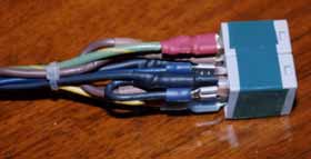
Closeup of an exposed relay assembly (this is a pair of relays fully assembled with the wire harness attached, before the outer insulating shrink tubing is in place). |
|
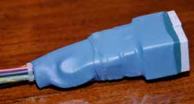
The same relay assembly after the outer insulation is in place - just drop it in your console and hook it inline. |
|
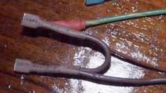
A closeup of one of the spliced leads for the relay harness (to illustrate the extents gone to for a quality assembly). The larger wires are 14 AWG (to carry current for the windows), and the small lead is 16 AWG (which carrys low current to the switch). Shrink tubing is used throughout for splice insulation as well as insulation over some spade connectors. The only place electrical tape is used is for holding the relay pair together -- and later in assembly, they're encapsulated in shrink tubing and wrapped with a large gauge wiretie to ensure they stay together. |
|
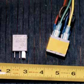
Measurement of the relay assembly, as well as one of the Bosch relays all by itself. Note how small it all is. This is rated 20A - which is higher than the fuse rating for the windows, so you're in good shape. |
|
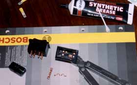
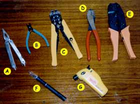
A variety of tools are necessary for a complete assembly of the relay kit. (A) My trusty needlenose Leatherman tool - or some other needlenose pliers, necessary for pushing some of the smaller connectors onto the relay terminals (which are pretty thick). (B) a good pair of sidecutters, for trimming wire. (C) wire insulation strippers - this is a keen tool because it consitently strips JUST the insulation from the wire, never nipping the wire itself. (D) a good heavy gauge wire cutter (for clipping the 14 AWG to length - using the fine sidecutters would damage them) - this particular snipper also has pretty decent crimping contacts. (E) a Palladin multi-tool crimper -- with insulated crimper insert - this is a ratcheting crimp tool, and ALWAYS nakes a good crimp. (F) X-Acto razor pen, used to cut the insulation from the inline splices on the ground leads (the stripper tool still stripped the insulation, but on an inline splice, the insulation tends to just bunch up). (G) a butane torch, used for shrink tubing, as well as heating up the wire in splices to improve the flow of solder into the joints. |
|
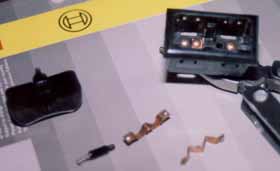
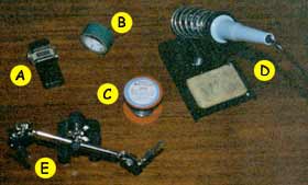
The soldering tools for the job. (A) a windproof lighter (used for shrinking the shrinktube on the prototype and early installations). (B) electrical tape (used for retaining the relay pairs during assembly). (C) 60/40 Ersin multicore .040" solder - virtually all connections are solderered after crimping, and wire splices are wrapped and soldered before being insulated. (D) 20W Weller soldering iron - this one happens to have a fine tip usually used for electronics - you'd normally want a more blunt tip. (E) swiveling dual-aligator clamp - extremely useful for holding wires while you solder them. |
![[TOP]](/graphic/JagUpBar.gif)
Sean B. Straw
EMail to: Sean.Straw+Jaguar@mail.professional.org